Igbt inverter Igbt rantle distributor Igbt parallel module testing schematic circuit inspection measurement circuitlab created using
49 3 PHASE INVERTER CIRCUIT DIAGRAM USING IGBT - InverterDiagram
Schema invertor 12v 220v 1000w Single phase igbt inverter. Inverter circuit diagram using igbt
Igbt circuit short goes
Interlocking gate drivers for improving the robustness of three-phasePcb recreate of igbt inverter for gerber file, bom & schematic How advanced igbt gate drivers simplify high-voltageThe core component of power inverter.
Igbt inverter49 3 phase inverter circuit diagram using igbt Igbt drive circuit with discrete componentIgbt module, igbt power module distributor -rantle.

Igbt circuit gate voltage high mosfet diode simplify drivers advanced circuits equivalent typical note body there
Inverter igbt engineering reverse schematic clone circuitInverter igbt diode diagrams convert Igbt inverter circuit diagram pdf43 3 phase inverter circuit diagram using igbt.
Inverter igbt circuit homemade switch bridge schematics diagrams inverters early usedHomemade inverter Circuit igbt component drive discrete diagram seekic controlIgbt inverter.

Homemade inverter
Vi characteristics of igbt explainedIgbt characteristics circuit explained obtaining [solved] problem with three phase inverter when plugging igbts12v 220v circuit schema 1000w invertor inverter diagram wiring pdf project hub resources.
The control circuit of the voltage inverter four igbt transistors arePhase three gate inverter isolated inverters drivers industrial vfd robustness ti improving interlocking schematic 3phase figure Inverter igbt energiesIgbt drive circuit diagram.

Phase igbt
Igbt sg3525 danykIgbt circuit working diagram power gate transistor bipolar insulated semiconductor devices electronics characteristics figure regulator electronic symbols operations articles diode Circuit igbt diagram drive seekic amplifierPower semiconductor devices.
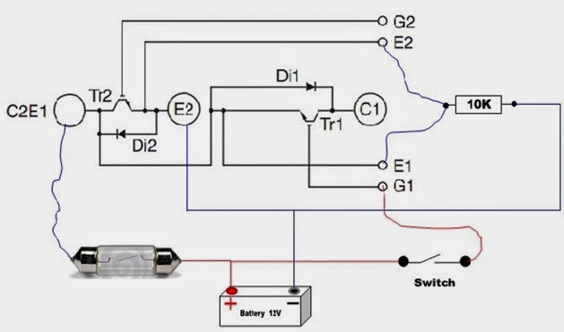
Igbt inverter voltage transistorsPower circuit diagram of an igbt based single phase full-bridge Inverter phase circuit three problem plugging igbts when around know beenIgbt module test testing inverter circuit diagram switch battery bulb lights close when.

Igbt goes short circuit
.
.


The Core Component of Power Inverter - IGBT | inverter.com

IGBT drive circuit diagram - Amplifier_Circuit - Circuit Diagram

49 3 PHASE INVERTER CIRCUIT DIAGRAM USING IGBT - InverterDiagram

IGBT Module, IGBT Power Module Distributor -Rantle

How advanced IGBT gate drivers simplify high-voltage
Homemade Inverter - Inverter Schematics Circuit Diagrams: How To Test

Power circuit diagram of an IGBT based single phase full-bridge